Basic repair of the Aldingen lock
Initial situation
Almost all important federal waterways in the south and southwest of Germany are already navigable by ships with a length of 135 meters. The Neckar is an exception here, as the lock facilities are only designed for smaller ships. Originally, the federal government planned to lengthen all 27 locks on the Neckar. In the meantime, however, it has been decided to forego an extension at all locations - including Aldingen - for the time being. In Aldingen, therefore, only the left lock chamber was fundamentally repaired in order to adapt it to today's technical requirements and ensure safe operation in the long term.
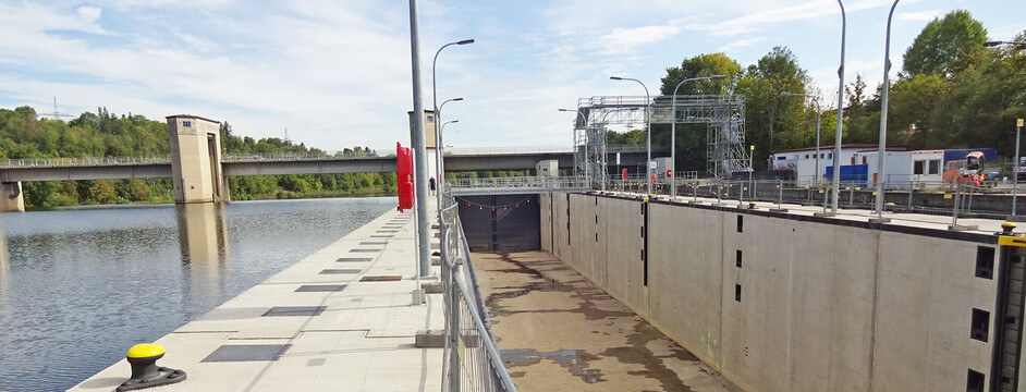
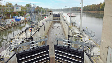
The Aldingen lock stage on the Neckar consists of a double-chamber lock, a weir with two fields and a power station. The lower head of the lock is spanned by a weir bridge with a public road, which is also used for cable crossing. The left lock chamber was completed back in 1938. Its electromechanical drives for the upper and lower gates date from 1957 and have thus been in operation for several decades. The construction of the right lock chamber began in 1941 but had to be interrupted due to World War II and was completed in the early 1950s, which means most of the components are more than 70 years old. Time has left its mark on the solid construction, the lock gates and the equipment technology of the entire lock system. Moreover, the technology no longer meets current regulations and is not suitable for remote control, hence the need for an overhaul. In addition, the lock was not designed for the standard 110 m long ships common in Europe, but can only accommodate ships up to 105 m in length.
Task
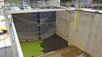
Since both lock chambers in Aldingen have been in operation for many years, the right lock chamber was first statically reinforced so that it can be available for shipping during the overhaul of the left chamber. The chamber walls of the left lock chamber received a new facing shell and the upper head was moved by 3.6 m, allowing ships with a length of 110 m to pass through the lock stage in the future. The upper forebay was overhauled, allowing 110 m long ships to moor in the future. In addition, the lock heads were renewed, new mitre gate closures were installed, a rope impact protection system was added at the lower head and air bubbling systems to prevent ice were installed. Furthermore, the left lock chamber will be remotely controllable in the future.
DriveCon was responsible for planning the electrical engineering technical equipment and later took over construction supervision.
Services
The electromechanical drives for the upper and lower head, dating from 1957, were replaced with electro-hydraulic cylinders controlled via frequency converters. Electromechanically operated gate cylinders are used for opening and closing. In addition, each gate wing received a drive unit, consisting of a sub-distribution and control cabinets with the necessary components for controlling the drives. At the lower head, this drive unit was supplemented by a control cabinet for the rope impact protection system and a hydraulic unit. The entire drive technology was housed in newly constructed drive houses at the upper and lower head of the left mole. The existing drive houses and the lock service building including control stand on the central mole remain in operation for the right chamber.
The electrical, control, communication and video technology, dating from 1957, was completely redesigned and adapted to the requirements of remote control. A separate central control was provided for each lock chamber, to which the controls of the drives are subordinate. All control units are interconnected with an optical fibre ring. The technology will be housed in a new technical building and in the workshop building, so that the lock chamber can be remotely controlled in the future.
The power supply of the lock comes from the associated power station. Due to the changed power consumption, a new LVMD with a connection capacity of 207 kVA and several distributions and sub-distributions were installed in the existing workshop building. In addition, a branch to the old LVMD of the right chamber was provided to continue supplying it. The future modernisation of the right chamber was also taken into account and the necessary branches were planned. A UPS system with a bridging time of 15 to 20 minutes was integrated into the LVMD. In the event of power failure, the power supply will be provided by an emergency generator with 200 kVA, which was installed externally.
The drive houses, the low-voltage main distributions and the central control stand are air-conditioned and heated to ensure the availability of the electronic components. As part of the overhaul, the left lock chamber also received internal and external lightning protection, a grounding system and potential equalisation. In addition, both the outdoor lighting of the lock system and the interior and safety lighting of the buildings were renewed. Another important point was the planning of the cable routes for the entire site and the performance of a risk assessment according to the Machinery Directive.
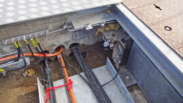
Challenges and special features
In the course of the repair of the left chamber of the Aldingen lock, a possible later basic repair and possible extension of the right lock chamber was already taken into account. The existing lock bridge had to be used as a cable crossing. This required elaborate coordination work during planning and coordination and control tasks during execution. There were numerous interfaces to the existing structure, which also had to be elaborately coordinated to achieve the correct implementation.