Ladenburg flood barrier, replacement construction, electrical engineering
Starting position
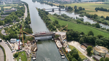
At Ladenburg, the Neckar federal waterway divides into the tributary canal and the river which cannot be used for ships. The weir system with the power station in the river and the flood gate at the entrance to the tributary canal form part of Ladenburg dam. The flood barrier is located downstream of the bridge on the L542 and protects the towns along the tributary canal from flooding. At the end of the Neckar canal, the ships return to river course through Feudenheim barrier.
The flood barrier gate was put into operation in 1931. Since then, the steel construction, the drives and the electrical engineering have not been modernised, but merely repaired if necessary. Replacing the flood barrier gate therefore became indispensable in order to continue to reliably protect the buildings and residents against flooding along the 7.5 km long Neckar canal.
The Task
The existing flood barrier takes the form of a double hooked gate and will be replaced by a new gate which will be installed a few meters downstream. Since the flood barrier gate needs to be ready for use at any time, a decision was made in favour of the robust and low-maintenance closure of a pressure segment. This new gate is closed when the water reaches a level of 5.8 to 5.9 m at which point navigation on the Neckar canal is prohibited. A drive house to house the control cabinets and drive technology was built on the south side.
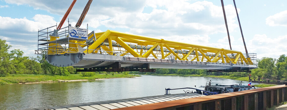
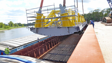
The gate itself was built in Roßlau shipyard and delivered to its destination by ship. During the entire construction phase, shipping on the Neckar canal needs to continue, which is why only short, pre-announced closures are possible.
It will not be possible to control the new facility remotely, but in an emergency it can be closed without electricity. The 16 million Euro replacement construction is considered to be the future standard for flood barriers on federal waterways.
Services
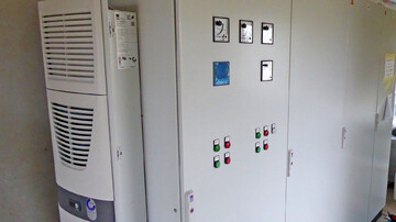
Within the scope of this project we took over the planning of the design and execution planning and the preparation of the tender documents along with the construction supervision for the electrical engineering trade. The planning services included the planning, design and dimensioning of the power supply to the flood barrier, the drives and the other ancillary systems. The possibility of feeding an external emergency power generator into the grid was also taken into account. This has a 11 kVA output to be able to supply power to the control system, sensors and lighting in the drive house for approx. 15 minutes, hence ensuring a controlled shutdown of the systems.
We also planned the technical control equipment and the hydraulics for lifting and lowering the barrier gate. The drives used are equipped with synchronisation monitoring and are switched on by soft starters. The systems on both sides of the canal are connected by an empty underground pipe culvert (5 x DN 110) through which the profibus, control and power cables run. What is more, the power supply for two flushing pumps was also planned in order to flush flotsam out of the gate niches.
A further part of our assignment involved the planning, conception and dimensioning of the earthing and lightning protection system, consisting of external and internal lightning protection, as well as the equipotential bonding for the lightning protection. A lightning protection risk management system was devised for the lightning protection system in accordance with the lightning protection standard. The earthing system also took into account the connection of the sheet pile walls. We also planned the lighting for the access routes, stair tower and drive house and searchlights. Furthermore, a risk assessment according to the Machinery Directive was carried out for the flood barrier gate.
Challenges and special features
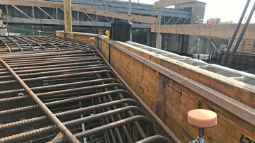
The counterpart to the lowerable high-water barrier forms a jamb wall in the canal sole, upon which the gate sits in the closed position thus protecting the side canal from flooding. Usually a jamb wall is built by closing the waterway and building a dry excavation pit. However, this would result in the waterway being blocked for several months. In order to circumvent a similar situation, a "prefabricated jamb wall" was developed, which was then lifted as a concrete block using a floating crane. This new variant meant that the closure times for shipping could be shortened considerably. However, this approach did come with several planning and organisational challenges. Another special feature is the limited space available on site, which had to be taken into account in the planning.
Availability plays an important role in a flood barrier, since the protective facility is only used a few times a year, and then mostly for routine tests. In the event of a flood, the flood barrier gate needs to be closed very quickly in order to prevent flooding. It therefore needs to be ensured that the facility is always ready for operation in case of flooding. This is guaranteed by having several fallback levels available with redundancies for power supply and operation. In the event of a power supply outage therefore, an emergency power supply system is activated and in the event of a PLC control system outage, emergency operation of the hardware.
