New lift bridge in Mittersill
Starting position
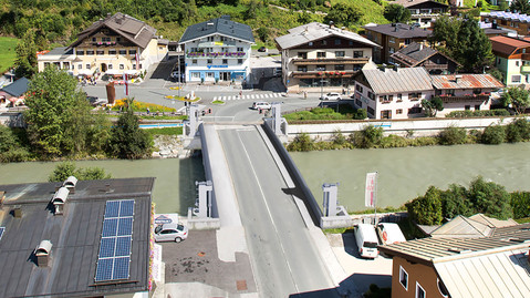
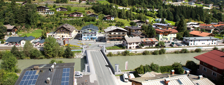
The river Salzach flows as a canal through the town centre of Mittersill and is spanned by Salzach Bridge which forms part of the B165. In the event of flooding, the reinforced concrete bridge stands in the run-off cross section and dams up from a HQ10. Although the bridge railing is removed when there is danger of flooding, there are still frequent blockages and therefore damage to the existing buildings. Since the water cannot run off unhindered, the headwater also accumulates, which in turn leads to the town flooding.
The Task
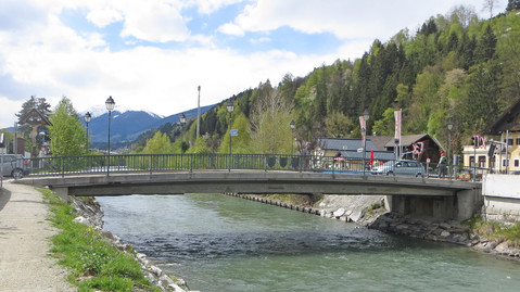
In order to reduce the future risk of flooding and to increase the run-off cross-section, a lifting bridge was built which can be raised electromechanically (electric lifting cylinders) up to 1.8 m during flooding. However, this also means that wires and cables can no longer be routed across the bridge from one bank to the other. An underground culvert was built for that purpose in the spring of 2016. DriveCon was responsible for planning the electrical engineering equipment for the lift bridge.
Services
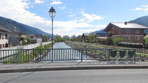
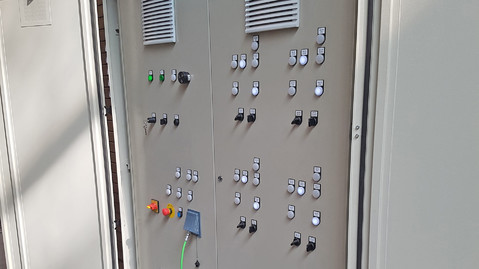
A supply line was laid from the distribution network operator to the meter column, through which the control cabinet is supplied with power. Since the control cabinet is outdoors, it was designed to be flood-proof with a raised base, lockable and weatherproof. The latter is achieved by an inner and outer control cabinet that results in a heat buffer and additional control cabinet heating. In the inner switch cabinet, the power supply can be switched over with a main switch to enable emergency power operation. In the event of a power failure, an emergency power generator can supply the bridge with power.
Part of the bridge is composed of four pylons, each of which is equipped with an electric lifting cylinder (4 x 3.0 kW) for the lifting movement of the bridge and for locking it in the upper position. Each of the lifting motors is fitted with a heater to prevent the formation of condensation and ice. PLC and frequency converters are used to control the bridge. Frequency converters allow the lifting drives to run synchronously and stop the bridge tilting. For emergencies, the control technology has been designed redundantly so that in the event the control system or the frequency converters fail, the electric lifting cylinder can be controlled over a contactor circuit. The locking drives are also controlled over a contactor circuit. The four operating modes - automatic mode, set-up mode, emergency mode and manual mode (without power, e.g. with a hand crank) - mean that the system can be used at any time. It can be operated with a touch panel, a control panel and in manual mode. What is more, the software for the remote control of the bridge has already been prepared so this can be easily realised at a later date.
Optical and acoustic warning devices were planned to announce the raising and lowering of the bridge. In addition, the earthing system, lightning and surge protection as well as the lighting for the roads and pavements were designed and a risk assessment of the entire system was carried out.
Challenges and special features
Since floods occur very quickly in this area, the bridge must be ready for use at all times. High redundancies are required to ensure this. These were made possible by several fallback levels in the operating modes (normal, manual and emergency operation) and by an emergency power generator. The construction yard was already equipped with emergency power generators, which, if needed, were to be used for the bridge. However, the performance of the bridge drives exceeded the capacity of the generator, so a special design for the frequency converters and motors was necessary. As a result, the lifting time in emergency power mode is approx. 30 minutes and in normal mode approx. 15-20 minutes.
