New construction to replace the Obernau barrier
Starting position
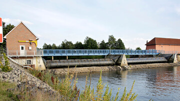
The Obernau barrier, consisting of a 3-field weir, a lock and a power station with fish ladder, was built between 1927 and 1930. The system is in a poor structural condition which is why it needed to be repaired. A repair would have resulted in considerable restrictions for shipping, which is why a more economical alternative was sought.
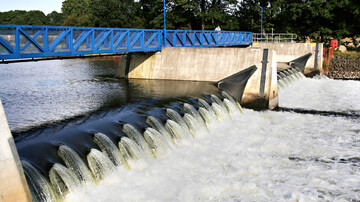
A variant study was conducted to examine and evaluate various construction measures. The final decision was made to construct a new lock and by doing so rebuild the weir system as an inflatable rubber dam with a fish ladder. With an inflatable rubber dam, a multi-layer membrane is attached to a weir plate using clamping rails and bolts. The resulting space is filled with air or water.
The Task
Between the existing lock and weir field 3, a new remote-controlled lock (basin length: 300 m, basin width: 12.5 m) will be built with a caulking gate at the lower head and a rotary segment gate at the upper head. Next, between the new lock and the new weir, a pleasure boat lock with a 20 m long and 4 m wide basin is being built. Both locks will be provided with new outer harbours in both the upstream and downstream sections to ensure that sufficient waiting places are available. The construction of the new lock on the water side next to the existing lock means that a new remote-controlled weir system, a power station canal, a fish ladder and a descent system including a watercourse with a channel have to be built underwater. A barrier-free jetty will stretch across the power plant canal, the weir fields and the two locks so that pedestrians and cyclists can cross the River Main. Following the commissioning of the new structures, the old lock will be kept operational for another 5 years after which it will be gradually filled in.
Services
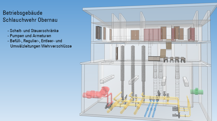
The object of the contract is planning services for the technical equipment for a water-filled inflatable rubber dam with central plant technology in the lock operation building, a lock and a pleasure boat lock. The existing lock, as well as two of the three existing weir fields, have to remain functional during the construction phase, which is why they need a provisional supply of electricity. Temporary solutions were planned to establish how this is possible and which cable routes need to be used for this purpose.
To supply power to the new lock and the weir, each of the power plant distribution systems will be equipped with a separate low-voltage outlet, both of which will be fed into the lock operation building. This is where the main low-voltage distributions for the lock and the weir system are to be installed. The LVMD for the weir is laid out with approx. 100 kVA, the LVMD for the lock with approx. 380 kVA. Since the controls for the weir and lock are also designed separately to each other, two distinct technical systems for power and control exist in the end.
In addition to the power supply, we also prepared a power distribution and energy balance report for each weir and lock to determine the power required for the consumers connected to the respective sub-distribution. We considered several scenarios here in order to determine performance peaks and design the systems accordingly. For emergencies, the lock is equipped with a 20 kVA UPS system and a bridging time of 240 minutes. The weir system is protected by a 9 kVA UPS. The emergency power supply from the power plant provides the emergency power supply for the weir. In addition, a feed-in option for a mobile emergency power generator was taken into account in the planning.
The commissioned services also included the network calculations for the weir and the lock, the dimensioning of the cables, the preparation of cable layout plans, the cable route planning and the associated cable length calculation. Attention was paid to a strict separation between the power and control cables. The pumps, fittings, pipelines and regulation shafts for the weir system also formed part of the assignment. Other parts of the assignment were planning the control of the weir system, the lock and the boat lock, and the power and control cables needed for it. It was important that both the lock and the weir system had to be capable of being controlled remotely.
Switch cabinet lighting including sockets, switch cabinet heating, fans, thermostats and hygrostats were provided for all switch cabinets depending on location and purpose. A level system and the height control of the weir gates were also planned as a triple-redundant system using pressure probes. We developed the technical equipment for the filling and emptying system of the weir hoses.
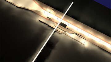
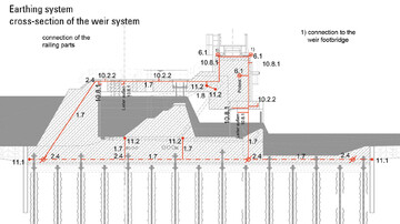
Furthermore, we planned the earthing for the weir and the locks, including the upper and lower outer harbours, and the light, signal and camera masts. Our lightning protection specialist developed a lightning protection system and dimensioned the surge protection and potential equalisation. A lighting calculation was carried out and a risk assessment for the boat lock, the lock and the weir was prepared.
Challenges and special features
Inflatable rubber dams are currently a rarity still on German federal waterways. Since 2006, five systems with locking heights of up to 2.5 m have been built. The replacement of the weirs at Obernau am Main, Neckarsulm and Beihingen am Neckar, each with a dam height of over 4.5 metres, therefore heralds a new era. The new closure system is accompanied by further changes, since inflatable rubber dams do not need mechanical drives, but are regulated by the water pressure and filling quantity in the hose.
