Overhaul and extension of the left chamber of the double chamber lock at Pleidelsheim
Starting position
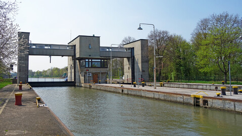
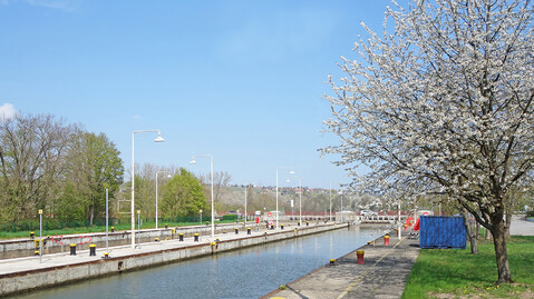
The double chamber lock at Pleidelsheim on the Neckar was completed in 1955 and has two chambers, each with a usable length of 110 m and a width of 12 m. In the meantime, the drives were equipped with frequency converters and the gates were upgraded; however, the electrical engineering has not yet been renewed and is therefore outdated. Moreover, the concrete surface of walls and levelling is heavily damaged. In addition, chamber walls and heads have water-bearing cracks, necessitating repair on the solid construction.
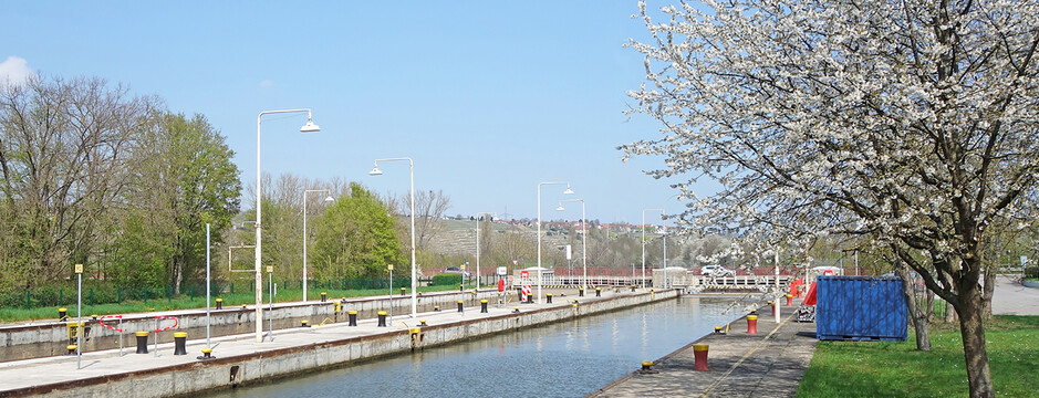
Since the late 1990s, ships with a length of 135 m have been using sections of the Neckar. Therefore, as part of the overhaul, the left chamber of the Pleidelsheim lock is to be extended to have a usable chamber length of 140 m. The system is thus part of the overall project "Expansion of the Neckar locks from Mannheim to Plochingen". By 2050, all construction measures should be completed and the Neckar federal waterway will be navigable for 135 m long ships throughout. The total costs for the expansion amount to approx. €1.2 billion.
The Task
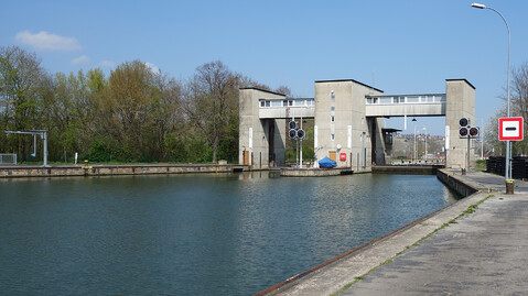
Since the lower heads of the lock are spanned by a road, the extension of the left lock chamber can only be done towards the upper water. For this purpose, the existing lift gate will be removed and replaced by a new pressure segment gate after the chamber extension. Furthermore, a new forebay in the upper water will be created. The forebay in the lower water will be rebuilt for larger ships. In addition, the entire electrical engineering will be renewed.
Services
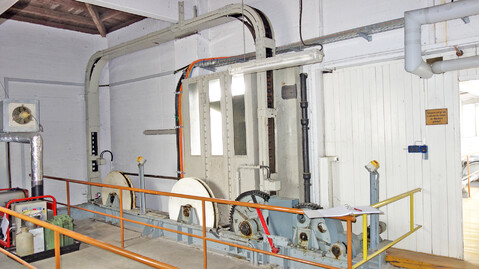
A new technical building will be constructed on the land side of the right lock chamber. Among other things, it will house the power supply, the LVMD and the emergency power supply. The building will also serve as a local control station and provide the possibility of converting to remotely controlled lock operation. A video system and a public address and intercom system are also planned to be able to view the lock and communicate with inland skippers on-site in case of remote control. Electric lifting cylinders with frequency converters will be used as drives for the lock gates.
Due to the extension of the left chamber, a reorganisation of the technical equipment is necessary, so the power supply, distribution and the control and automation system are being newly planned by us. Since the existing LVMD does not meet the increased power demand and the desire for remote control, a new LVMD will be created in the technical building; the power supply will continue from the existing transformer. To distribute electrical power, the existing LVMD will be connected to the new LVMD (connection capacity 250 kVA). A separate sub-distribution will be created for all drive houses to supply the controls and drives. Furthermore, a UPS will be integrated into the LVMD to supply the lock control and sensors. The technical building will also accommodate operational requirements in the form of social and sanitary rooms. In addition, we provide planning content for plant groups 1, 2 and 3 (sewage, water and gas systems, heating supply systems and air conditioning systems) for the technical building.
Both the interior of the technical building and the exterior area on the lock premises will be planned with LED technology lighting. The drive houses, the LVMD and the central control stand will be air-conditioned to ensure the smooth functioning of electrical components. Heating for the premises and their ventilation and extraction will also be considered.
The grounding system no longer meets current standards and will therefore be adapted to current requirements and regulations. In addition, a lightning protection concept for internal and external lightning protection will be developed and proper equipotential bonding will be planned. Our contract also includes the planning of traffic light systems and nautical radio communication as well as the execution of a risk analysis according to the Machinery Directive.
Challenges and special features
During the modernisation and extension of the left lock chamber, the continued operation of the right lock chamber must be ensured. Therefore, extensive construction sequences and temporary solutions had to be planned in advance for electrical engineering and numerous other trades.
Another special feature is that this project is being processed using the BIM method. Here, we contributed to the existing model as well as the new construction model with corresponding LODs.